TEMPSENS
CENG 317
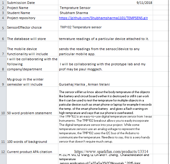
TMP102(Temperature Sensor)
Week13
PRESENTATION
(https://github.com/Shubhamsharma1101/TEMPSENS/files/2621924/Tmp102.Temperature.sensor.pptx)
Week12
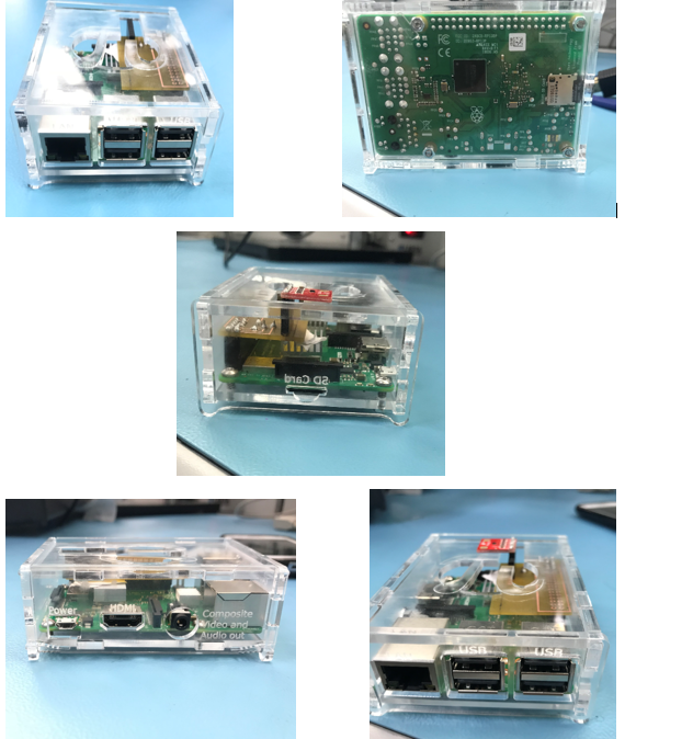
ENCLOSURE
This week was case design due. After I recieved all of my parts from the prototype lab I assembled them together with my PCB and RASPBERRY PI inside it . I kept my sensor out of the case cause I think it might affect the readings. All my parts are enclosed properly, easily accessible and securely attached.
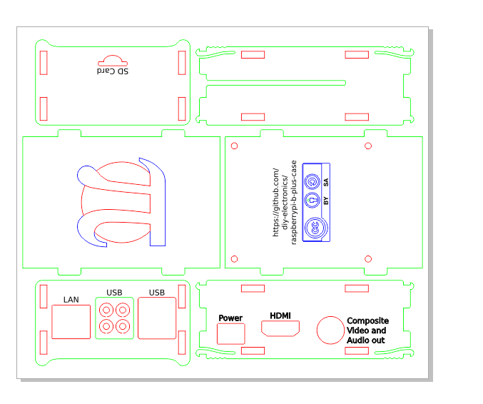
CASE DESIGN
Week 11
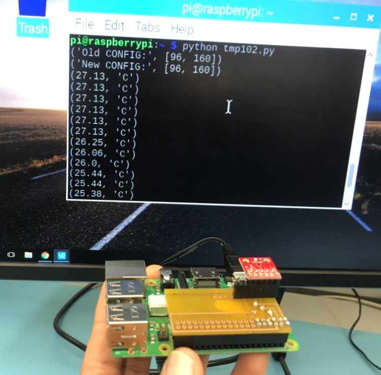
PCB POWER UP
PROGRESS REPORT
This week was PCB power up Milestone I already tried to finish up with that during my weekend . For this I had to first learn some PYTHON language as I had never done that before.I searched on google for my code so that I have my readings on my sensor and tried alot of things by watching a You tube video as well. I followed all the steps as shown in the video and was able to get the reading . The reading that i got was in hexadecimal . So I had to convert my hex value to dec I searched for it on google tried different ways to get upon that but was not able to figure it out. Finally sparkfun gave me a hope they also had a code for my TMP102 sensor i followed all the steps in class and this was giving me a Remote I/O error so i googled how to get rid of the error and was successful .Then I rubbed my hand and covered the sensor with my fingers and it was showing change in temperature.Also on blowing air from the mouth it shows a change in the readings.
## CODE
https://learn.sparkfun.com/tutorials/python-programming-tutorial-getting-started-with-the-raspberry-pi/experiment-4-i2c-temperature-sensor
Week 10
PCB soldering
PROGRESS REPORT:-
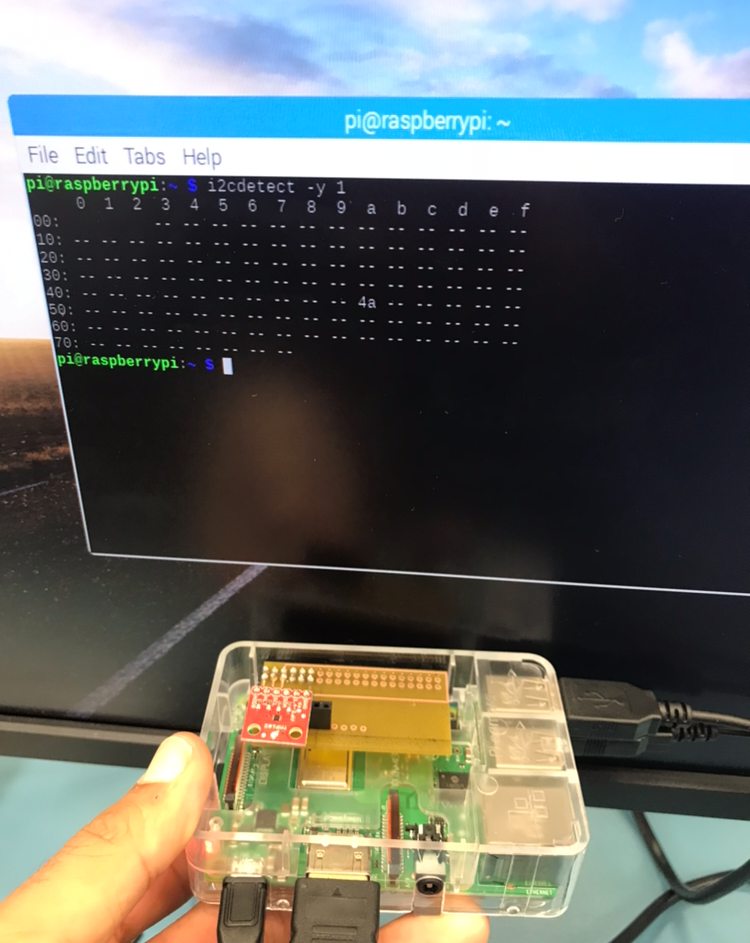
So it is week 10 and I got my PCB today from the prototype lab. I was late in getting it because when i went on monday to confirm that wheter my PCB is done but vlad told me that they havn’t recieved any email under my name then I showed him the mail I had sent and he replied that it must be stuck in a spam or something like that and told me to re-send it again. So I got it on tuesday and did my soldering in the class.To connect my sensor to PCB I bought header pins for my sensor from the prototype lab. Once soldering was done so I tried to obtain my i2c address by connecting my PCB to the Raspberry and i was successful in doing it.
So no additional expense was added in my original budget.
Week 9:
PCB design
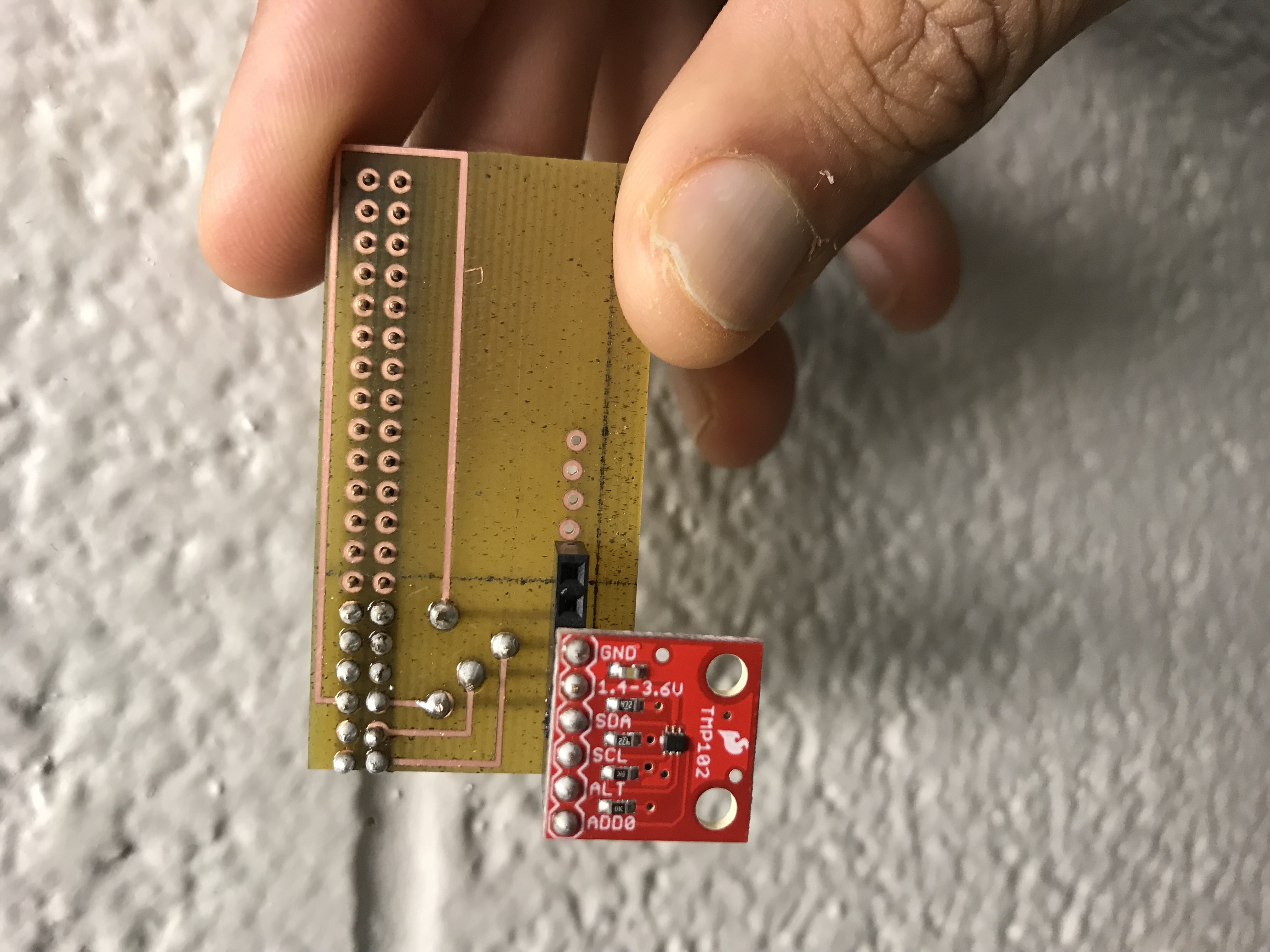
So its end of week 9 and i am pretty much done with half of my project .I have designed my pcb i used a 12 header pins because all my pins that were to be connected were not in single line. So I uploaded two pictures one with the sensor and one with the 12 header pin. And i have sent my gerber files to prototype lab so that they can give my designed PCB.
Week 8:
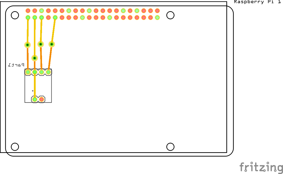
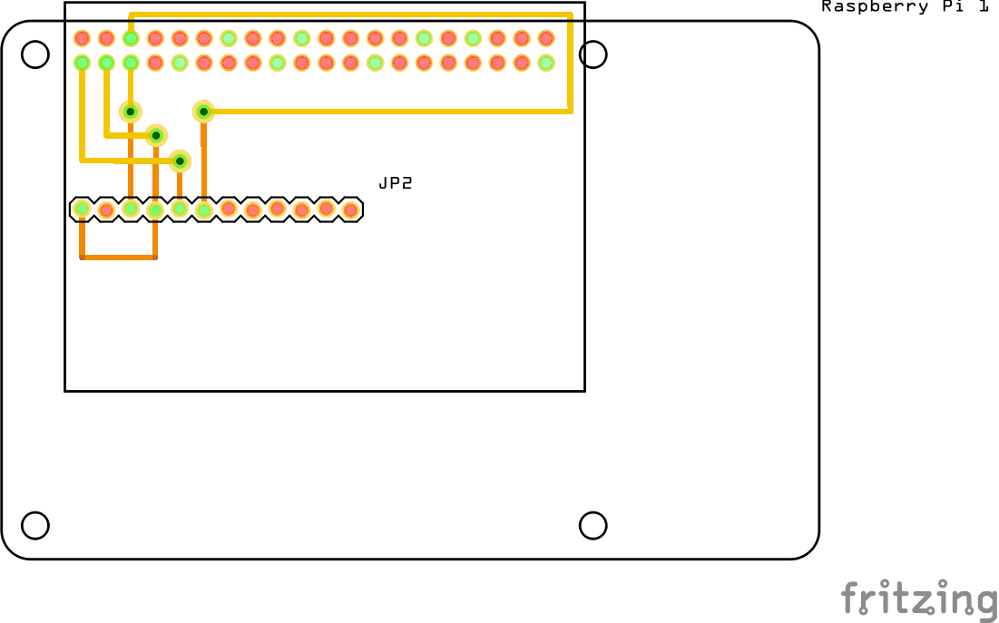
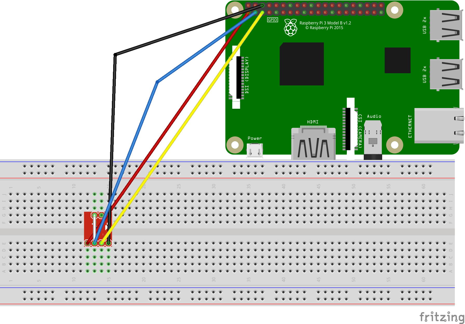
Fritzing Diagram
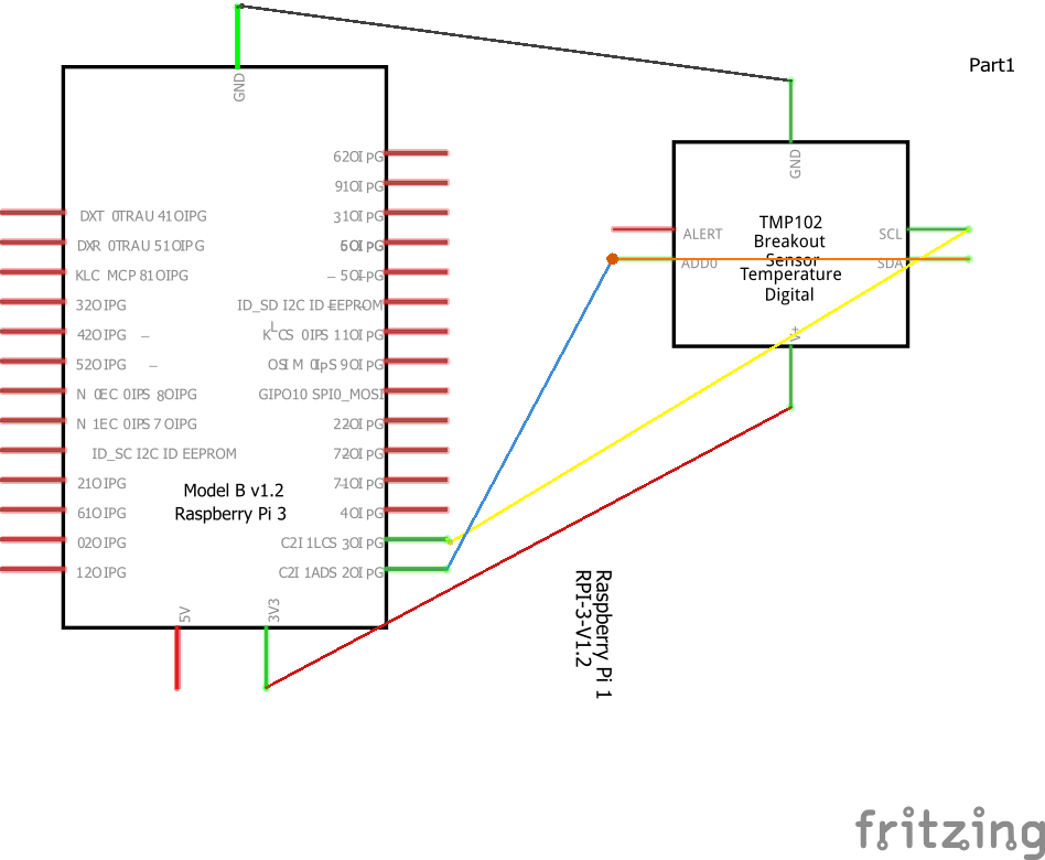
Schematic Diagram
Breadboarding
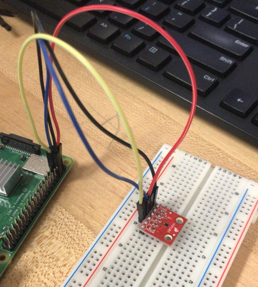
Working
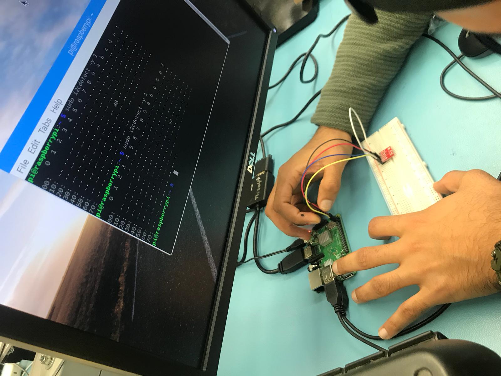
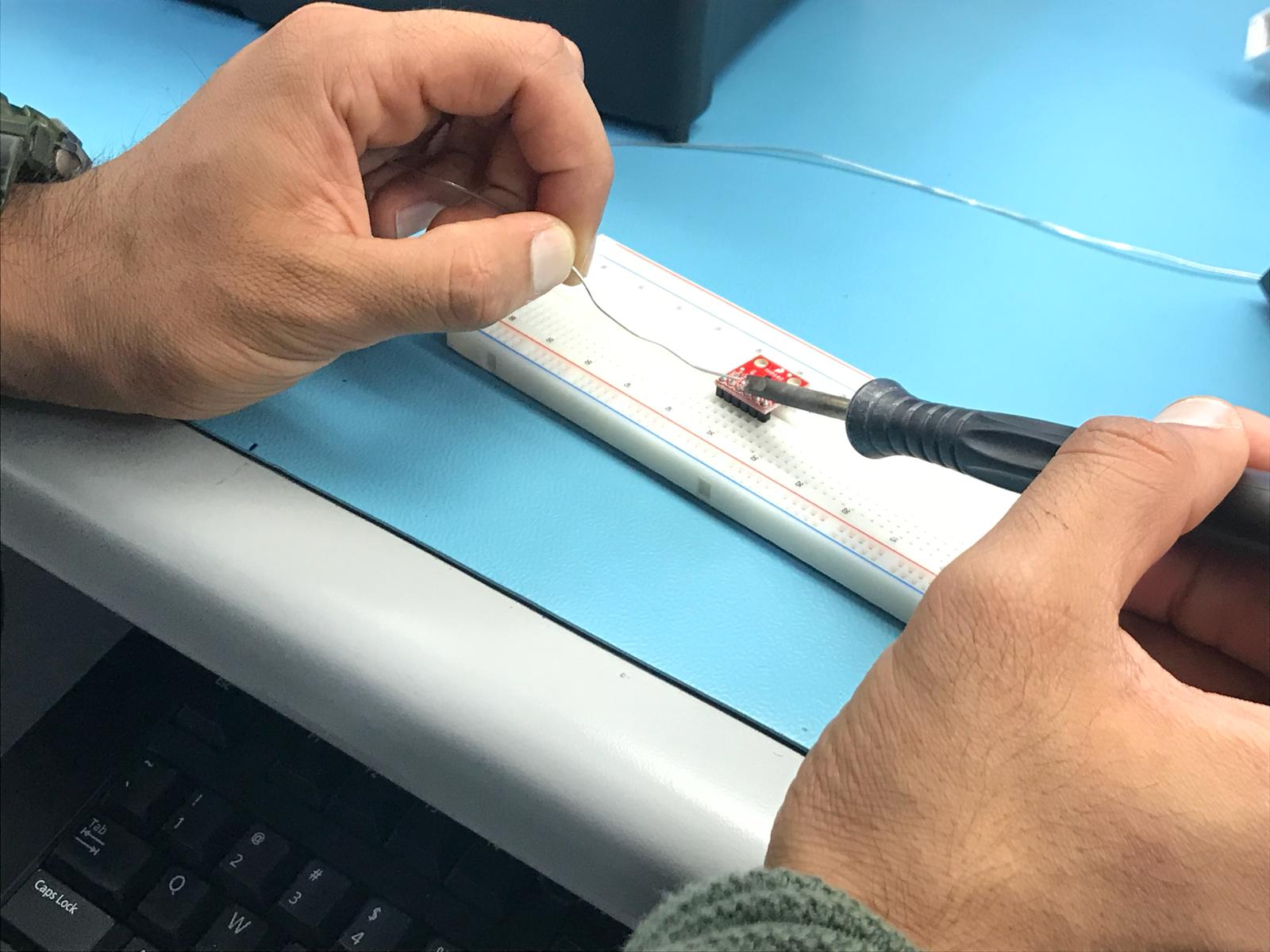
This week i connected all my wires from the sensor to the breadboard and then connected it to my raspberry pi . Also you can see in the picture there is my i2c address on the rpi terminal. Before it was showing me address (48) instead of 4a when i connected all my wires and made the connection for RPI terminal connection. Then I added one more wire (IN PICTURE WHITE WIRE) i.e address wire which goes from SDA to ADD0.
Week7:
Soldering
Pseudo Assignment(UML)

Week5:
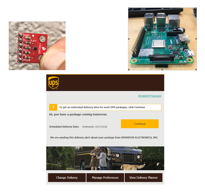
Parts recieved
I Recieved my raspberry pi within two days after ordering. However I recieved my sensor on thursday 18th of october due to some delivery issue.
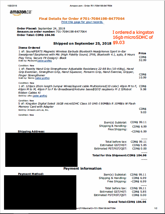
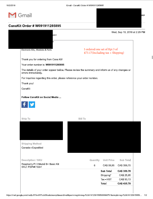
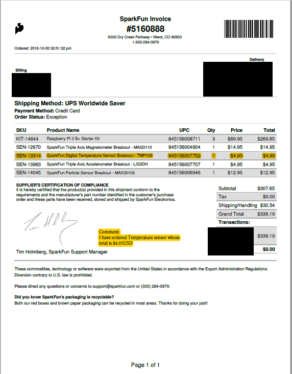
Proof of Purchase
SD card
Raspberry PI
Temerature Sensor
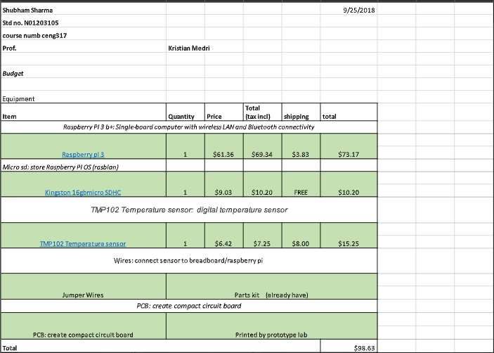
Week4
Budget
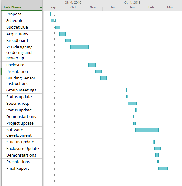
Week 3:
Schedule
Week 2
PROPOSAL